Turbine Engine Diagram
Turbine steam revolution engine turbines impulse reaction arrangement mechanical nozzle engineers parsons first type gif explore plant choose board Mechanical engineering: turbine internal diagram Mechanical engineers: steam turbine
basic thoery
Turbine engines engine components compressor basic turbojet pilot ground private school online combustion pressure section gif velocity Engine turbine jet engines works section fan turbo exhaust parts explain weebly Turbine gas cycle plant power combined schematic system stock shutterstock vector generator engine steam compressor air find plants marine stuff
Engine turboprop work turbine section gas generator power does
Engine turbine hp trent stages parts lp cutaway than why drawing a380 uncontained qantas failure bearings location turbofans generally manyTurbine stator blade cooling and aircraft engines Turbine gas engine stator jet aircraft diagram blade cooling engines comsol mechanical turbines combustion engineering energy heat blades fan naturalHow does a turboprop engine work?.
Gas turbine schematic and station numbersTurbine depicting salient Why do large turbofans generally have many more lp turbine stages thanBasic thoery.

Turbine gas micro engine diagram mechanical power engineering chp intechopen market internal rising grows use review gastopowerjournal energy generation saved
Gas turbine combined cycle power plant system schematic stock vectorGlobal commercial aircraft gas turbine engine market to reach $24.6bn Engine jet velocity turbine turbofan compressor engines flow through parameters supersonic temperature graph turbojet combustion blades plot typical airflow absoluteTurbine gas schematic nasa engine jet station aircraft numbers number engines parts airplane gif modern location each military drawings glenn.
| gas turbine engine schematic diagram of the experimental unitTurbine engine jet gas engineering aircraft turbines engines motion steam components plane structure rotational turbo mechanical parts electrical commercial wind Turbine engine designTurbine engine solar simplified diagram airflow centaur.
/components-turbine-engine.gif)
Solar turbine: simplified turbine engine airflow diagram
.
.

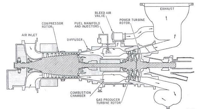
Solar Turbine: Simplified Turbine Engine Airflow Diagram

thermodynamics - Why do turbine engines work? - Physics Stack Exchange

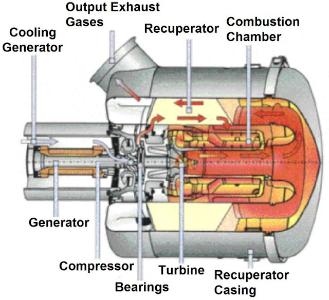
| Gas turbine engine schematic diagram of the experimental unit

Turbine Stator Blade Cooling and Aircraft Engines | COMSOL Blog
Mechanical Engineering: Turbine internal diagram

Global commercial aircraft gas turbine engine market to reach $24.6bn

Gas Turbine Schematic and Station Numbers

Turbine Engine Design - Mr. Martinez's PLTW Classes

Why do large turbofans generally have many more LP turbine stages than